扫一扫
关注中图网
官方微博
本类五星书更多>
-
>
闯进数学世界――探秘历史名题
-
>
中医基础理论
-
>
当代中国政府与政治(新编21世纪公共管理系列教材)
-
>
高校军事课教程
-
>
思想道德与法治(2021年版)
-
>
毛泽东思想和中国特色社会主义理论体系概论(2021年版)
-
>
中医内科学·全国中医药行业高等教育“十四五”规划教材
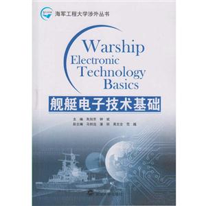
舰艇电子技术基础 版权信息
- ISBN:9787307188822
- 条形码:9787307188822 ; 978-7-307-18882-2
- 装帧:暂无
- 册数:暂无
- 重量:暂无
- 所属分类:>>
舰艇电子技术基础 本书特色
本书结合理论和实践,是海军工程大学模拟电路分析课程的配套英文教材。全书共12章,分别介绍模拟的概念、二极管、双极型晶体管、场效应管、放大器、滤波器、稳压器、振荡器和定时器、测量和控制电路、基本运放电路。书中穿插大量有趣的补充背景知识、丰富的例题、小节复习题和章末练习题。
舰艇电子技术基础 内容简介
全书共12章, 分别介绍模拟的概念、二极管、双极型晶体管、场效应管、放大器、滤波器、稳压器、振荡器和定时器、测量和控制电路、基本运放电路。书中穿插大量有趣的补充背景知识、丰富的例题、小节复习题和章末练习题。
舰艇电子技术基础 目录
IntroductionChapter 1 Diodes and Applications 1.1 Introduction 1.2 Ideal Diodes 1.3 Practical Diodes 1.4 Physical Operation of Junction Diodes 1.4.1 Diode Junction 1.4.2 Forward.Biased Condition 1.4.3 Reverse.Biased Condition 1.4.4 Breakdown Condition 1.5 Charactcristics of Practical Diodes 1.5.1 Forward.Biased Region 1.5.2 Reverse.Biased Region 1.5.3 Breakdown Region 1.6 Zener Diodes 1.7 Light.Emitting Diodes 1.8 Applications of Diodes 1.8.1 Diode Rectifiers 1.8.2 Clippers 1。8.3 Output Filters for Rectifiers Chapter 2 Amplifiers 2.1 Bipolar Junction Transistor 2.1.1 Principle 2.1.2 Input and Output Characteristics 2.2 Low-frequency Amplifiers 2.2.1 DC Biasing Circuits 2.2.2 Analyzing Methods of Amplifiers 2.2.3 Common-Emitters 2.2.4 Emitter Followers 2.3 Field-Effect Transistors 2.4 Cascaded Amplifiers 2.4.1 Input Resistance 2.4.2 Output Resistance 2.4.3 Voltage Gain of the Multi-stage Amplifier 2.4.4 Frequency Response of the RC-coupled Amplifier 2.5 Active Sources and Differential Amplifiers 2.5.1 Internal Structure of Differential Amplifiers 2.5.2 BJT Current Sources 2.5.3 Characteristics of Differential Amplifiers 2.5.4 Differential Amplifier Circuit 2.6 Power Amplifiers 2.6.1 Classification of Power Amplifiers 2.6.2 Class B Complementary Push-pull Amplifiers 2.6.3 Complementary Class AB Push-Pull AmplifiersChapter 3 Feedback Amplifiers 3.1 The Basic Concept of Feedback Amplifiers 3.2 The Principle of Negative Feedback 3.3 Feedback Topologies 3.4 Identifying the Type of Negative Feedback Amplifier 3.5 Approximate Calculation of AfChapter 4 Oscillators 4.1 Principles of Oscillators 4.1.1 Frequency Stability 4.1.2 Amplitude Stability 4.2 Phase-Shift Oscillators 4.3 Wien-Bridge Oscillators 4.4 Colpitts Oscillators 4.5 Hartley Oscillators 4.6 Crystal OscillatorsChapter 5 Operational Amplifiers 5.1 Characteristics of Ideal Op-Amps 5.2 Analysis of Circuits with Ideal Op-Amp 5.2.1 Inverting Amplifier 5.2.2 Noninverting Amplifier 5.2.3 Differential Amplifier 5.3 Applications 5.3.1 The Integrator 5.3.2 The Differentiator 5.3.3 Noninverting Summing Amplifier 5.3.4 Inverting Summing Amplifier 5.3.5 Addition-Subtraction Amplifier 5.4 Active Filters 5.4.1 Low-Pass Filter 5.4.2 High-pass Active Filter 5.4.3 Bandpass Filter 5.5 Comparator 5.5.1 Basic Inverting Schmitt Trigger 5.5.2 Voltage Transfer CharacteristicChapter 6 Introductory Digital Concepts 6.1 Digital and Analog Quantities 6.2 Binary Digitals. Logic Levels and Digital Waveforms 6.2.1 Binary Digits 6.2.2 Logic Levels 6.2.3 Digital Waveforms 6.2.4 The PulseChapter 7 Number Systems. Operations. and Codes 7.1 Binary-to-Decimal Conversion 7.2 Decimal-to-Binary Conversion 7.3 Binary AdditionChapter 8 Logic Gates 8.1 The Basic Logic Gates 8.2 Fixed-Function LogicChapter 9 Boolean Switching Algebra 9.1 Boolean Operations and Expressions 9.2 Laws and Rules of Boolean Algebra 9.2.1 Laws of Boolean Algebra 9.2.2 Rules of Boolean Algebra 9.3 DeMorgans Theorems 9.4 Simplification Using Boolean Algebra 9.5 Boolean Expressions and Truth Tables 9.5.1 The Sum-of-Products (SOP) Form 9.5.2 The Product-of-Sums (POS) Form 9.5.3 The truth table 9.6 The Karnaugh MapChapter 10 Combinational Logic 10.1 Definition of Combinational Logic 10.2 Functions of Combinational Logic 10.2.1 Adders 10.2.2 Encoders 10.2.3 MultiplexersChapter 11 Latches. Flip-Flops and Timers 11.1 Latches 1 1.1.1 The S-R (Set-Reset) Latch 11.2 Flip-Flops 11.2.1 The Edge-Triggered S-R Flip-Flop 11.2.2 The Edge-Triggered D Flip-Flop 11.2.3 The Edge-Triggered J-K Flip-Flop 11.2.4 Flip-Flop Applications 11.3 One-shots 11.4 The Astable MultivibratorChapter 12 Counters and Shift Registers 12.1 Counters 12.1.1 Asynchronous Counters 12.1.2 Synchronous Counters 12.2 Shift RegistersAppendix A Testing Solid-state ComponentsAppendix B Answers to All the Problems
展开全部
舰艇电子技术基础 作者简介
朱旭芳,女,湖北天门人,1978年10月生,现任海军工程大学电子工程学院讲师,研究方向为电路与系统。曾在国内核心期刊发表多篇学术论文。
书友推荐
本类畅销
-
UG NX 10.0模具设计教程
¥38.2¥59 -
计算机组成原理(微课版)
¥45¥69.8 -
电路基础/于宝琦
¥31.9¥49 -
通信电源
¥23.9¥38.8 -
计算机操作系统-(第四版)
¥19¥53 -
科学技术概论
¥30.4¥49
浏览历史
AMSYS HFSS实战应用高级教程
¥47.6¥63.0线性代数(第二版)
¥29.2¥44.8反应堆热工水力学
¥26.8¥35.8结构动力学优化
¥59.8¥98.0机器人机构创新设计
¥47.9¥69.0


