扫一扫
关注中图网
官方微博
本类五星书更多>
-
>
湖南省志(1978-2002)?铁路志
-
>
公路车宝典(ZINN的公路车维修与保养秘籍)
-
>
晶体管电路设计(下)
-
>
基于个性化设计策略的智能交通系统关键技术
-
>
德国克虏伯与晚清火:贸易与仿制模式下的技术转移
-
>
花样百出:贵州少数民族图案填色
-
>
识木:全球220种木材图鉴
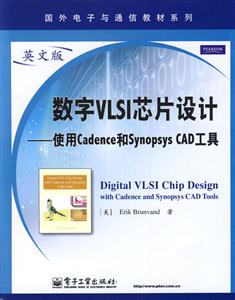
数字VLSI芯片设计-使用Cadence和Synopsys CAD工具 版权信息
- ISBN:9787121091599
- 条形码:9787121091599 ; 978-7-121-09159-9
- 装帧:暂无
- 册数:暂无
- 重量:暂无
- 所属分类:>>
数字VLSI芯片设计-使用Cadence和Synopsys CAD工具 内容简介
本书介绍如何使用cadence和synopsys公司的cad工具来实际设计数字vlsi芯片。读者通过本书可以循序渐进地学习这些cad工具,并使用这些软件设计出可制造的数字集成电路芯片。本书内容按集成电路的设计流程编排,包括cad设计平台、电路图输入、verilog仿真、版图编辑、标准单元设计、模拟和数模混合信号仿真、单元表征和建库、verilog综合、抽象形式生成、布局布线及芯片总成等工具;每一工具的使用都以实例说明,*后给出了一个设计简化mips微处理器的完整例子。本书可与有关集成电路设计理论的教科书配套使用,可作为高等院校有关集成电路设计理论类课程的配套教材和集成电路设计实践类课程的教科书,也可作为集成电路设计人员的培训教材和使用手册。
数字VLSI芯片设计-使用Cadence和Synopsys CAD工具 目录
1 introduction
1.1 cad tool flows
1.1.1 custom vlsi and cell design flow
1.1.2 hierarchical cell/block asic flow
1.2 what this book is and isn't
1.3 bugs in the tools?
1.4 tool setup and execution scripts
1.5 typographical conventions
2 cadence dfii and icfb
2.1 cadence design framework
2.2 starting cadence
2.3 summary
3 composer schematic capture
3.1 starting cadence and making a new
working library
3.2 creating a new cell
3.2.1 creating the schematic view of a full adder
3.2.2 creating the symbol view of a full adder
3.2.3 creating a two-bit adder using the fulladder bit
3.3 schematics that use transistors
3.4 printing schematics
3.4.1 modifying postscript plot files
3.5 variable, pin, and cell naming restrictions
3.6 summary
4 verilog simulation
4.1 verflog simulation of composer schematics
4.1.1 verilog-xl: simulating a schematic
4.1.2 nc_verilog: simulating a schematic
4.2 behavioral verilog code in composer
4.2.1 generating a behavioral view
4.2.2 simulating a behavioral view
4.3 stand-alone verilog simulation
4.3.1 verilog-xl
4.3.2 nc_verilog
4.3.3 vcs
4.4 timing in verilog simulations
4.4l behavioral versus transistor switch simulation
4.4.2 behavioral gate timing
4.4.3 standard delay format (sdf) timing
4.4.4 transistor timing
4.5 summary
5 virtuoso layout editor
5.1 an inverter schematic
5.1.1 starting cadence kfb
5.1.2 making an inverter schematic
5.1.3 making an inverter symbol
5.2 layout for an inverter
5.2.1 creating a new layout view
5.2.2 drawing an nmostransistor
5.2.3 drawing a pmos transistor
5.2.4 assembling the inverter from the transistor layouts
5.2.5 using hierarchy in layout
5.2.6 virtuoso command overview
……
6 standard cell design template
7 spectre analog simulator
8 cell characterization
9 verilog synthesis
10 abstract generation
11 soc encounter place and route
12 chip assembly
13 design example
a tool and setup scripts
b scripts to drive the tools
c technology and cell libraries
bibliography
index
展开全部
书友推荐
- >
小考拉的故事-套装共3册
小考拉的故事-套装共3册
¥36.7¥68.0 - >
莉莉和章鱼
莉莉和章鱼
¥19.7¥42.0 - >
随园食单
随园食单
¥15.4¥48.0 - >
我与地坛
我与地坛
¥15.4¥28.0 - >
上帝之肋:男人的真实旅程
上帝之肋:男人的真实旅程
¥19.3¥35.0 - >
月亮虎
月亮虎
¥15.4¥48.0 - >
月亮与六便士
月亮与六便士
¥13.4¥42.0 - >
推拿
推拿
¥12.2¥32.0
本类畅销
-
4.23文创礼盒A款--“作家言我精神状态”
¥42.3¥206 -
4.23文创礼盒B款--“作家言我精神状态”
¥42.3¥206 -
一句顶一万句 (印签版)
¥40.4¥68 -
百年书评史散论
¥14.9¥38 -
1980年代:小说六记
¥52.8¥69 -
中图网经典初版本封面-“老人与海”冰箱贴
¥20¥40


